WIRTGEN levelling systems
Levelling system LEVEL PRO / LEVEL PRO PLUS
Levelling in an automated process
In cutting and milling, it is crucial to
remove pavements to the specified depth. The intuitive WIRTGEN LEVEL
PRO / LEVEL PRO PLUS levelling technology can be relied on to precisely
maintain the preset cutting and milling depth. The hightech system is
fully integrated into the machine’s overall management system.
LEVEL PRO / LEVEL PRO PLUS continuously
reconciles the actual cutting and milling depth with the preset target
value. Any deviations detected by the system are levelled out
dynamically by means of proportional control. The actual cutting and
milling depth is determined by means of optical or mechanical sensors
scanning a reference surface.
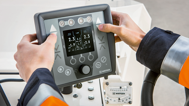
- The new LEVEL PRO / LEVEL PRO PLUS
levelling system offers intuitive, one-hand operation via a rotary
control and free menu configuration.
- Full integration of the LEVEL PRO /
LEVEL PRO PLUS levelling system into the machine management system
allows a high degree of automation.
- The LEVEL PRO / LEVEL PRO PLUS
levelling system offers many complementary and automated features which
relieve the operator of a part of his workload. This also results in a
faster progress of operations.
 |
 |
| LEVEL PRO / LEVEL PRO PLUS screen for small milling machines |
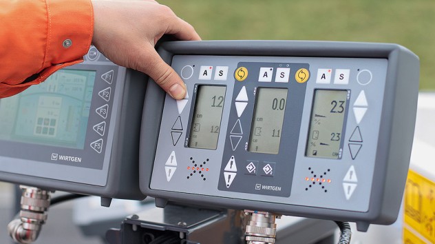
LEVEL PRO / LEVEL PRO PLUS screen for large milling machines |
The machine is adjusted in height via
the lifting columns of the front and rear wheel or track units, all of
which are interlinked hydraulically. If one of the wheel or track units
climbs over a hump or drops into a dip, the resulting difference in
height is levelled out automatically by the remaining three wheel or
track units. This fourfold full-floating feature enables the machine to
always align itself to the ground automatically, which results in
significantly improved machine stability.
Closely linked to this feature is the
PTS system (Parallel To Surface) integrated in the levelling system,
which aligns the machine parallel to the ground surface during the
milling process and supports the operator in positioning the machine in
the milling cut.
The integrated auto-start feature allows
the wheel or track units to be lowered to the specified depth
simultaneously at the mere push of a button; the milling drum penetrates
the material more slowly as a result. Manual adjustment of the rear
wheel or track units to maintain the specified working depth is no
longer required. Operation of the machine is simplified considerably at
the same time.
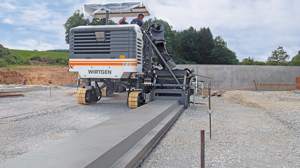
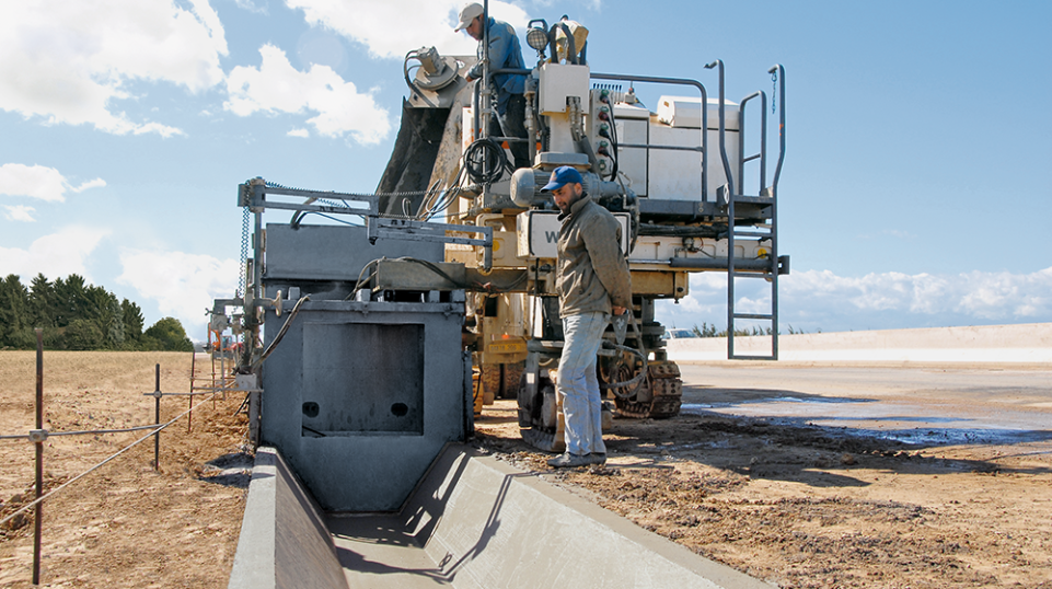
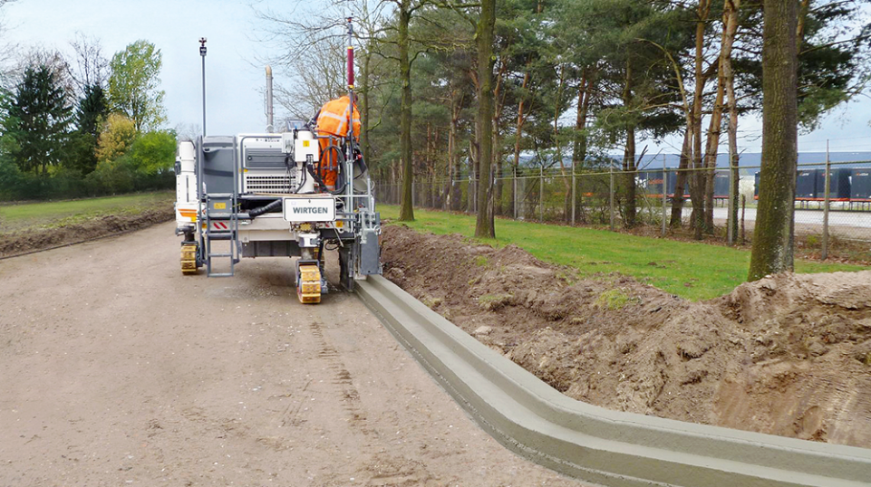
Automatic level and cross slope control
Paving thickness accurate to the millimetre
The levelling control system governs the
paving thickness of concrete profiles in accordance with a specified
reference. Slipform pavers typically use mechanical systems scanning a
stringline to effect horizontal position and level control.
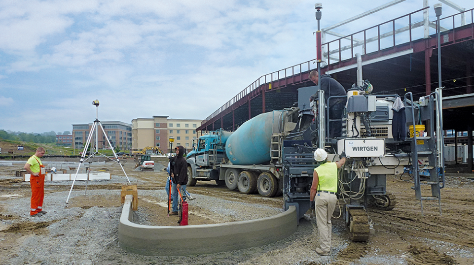
Stringless 3D control systems have also
proven their worth in recent years, however, and are sometimes even a
requirement today in tender specifications. 3D control offers many
advantages over stringline control – the ideal paving line, for
instance, need not be transferred to the actual construction site by
means of a wire but is available as a computer model. This digital
terrain model is used to define the set positions of the machine which
are then monitored using optical measuring systems such as a motorized
total station and prism. A wide variety of concrete profiles can thus be
produced to precision in a simple and efficient process.
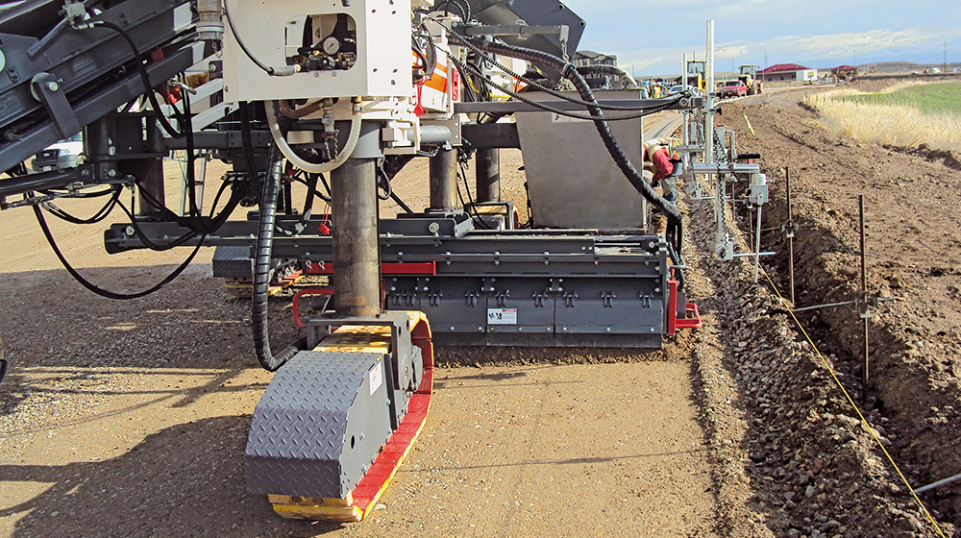
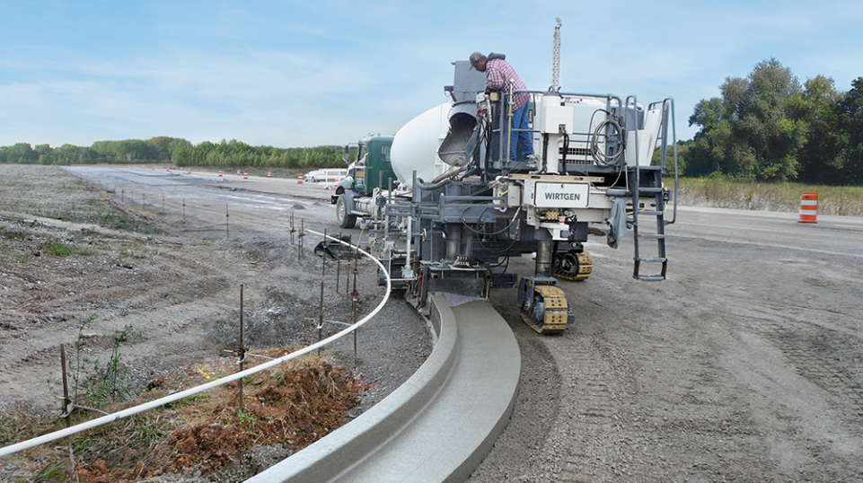
Level control using stringline
A stringline is carefully installed and
tensioned along the entire length of the concrete profile or slab to be
produced prior to commencing the paving operation. It will provide the
specified paving level. Two separate sensors carried by the slipform
paver normally guide off the stringline for level control – one sensor
for the front tracks, a second one for the rear tracks. While the
slipform paver keeps moving forward, both sensors scan the stringline
and continuously send pertinent level details to the paver’s control
system. These level details are not absolute values, however, but merely
the deviations from the set value that is provided by the stringline.
The control system receives the measured
results, and in case of any deviation actuates the relevant hydraulic
cylinders to compensate by adjusting the level of the machine including
the mould. This matching process takes place around 40 times per second.
The side of the paver carrying the mould is immediately raised or
lowered by the resulting difference between the actual and set values.
The opposite side of the machine is balanced in level by means of a
second control loop with integrated slope sensor.
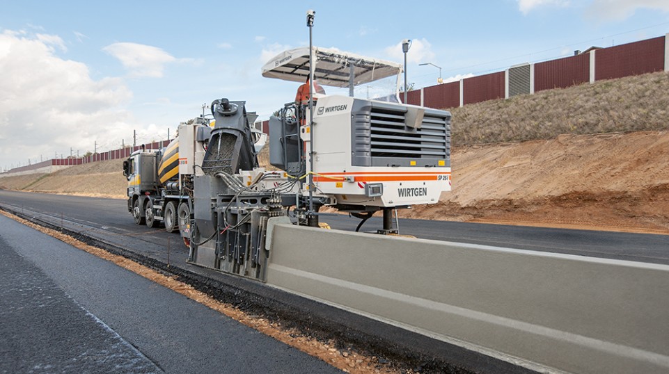
Level control using a 3D system
With stringless systems, the computer of
the 3D control system feeds the paver’s control system with the
specified parameters of level and horizontal position of the concrete
profile to be built. The 3D system uses a special interface to
communicate with the controller of the slipform paver.
Two prisms are typically installed on
the slipform paver which have direct visual contact to a total station
each, reflecting their optical beam. The total station keeps determining
the prism’s current 3D position. The measured results are transmitted
by radio to the system computer on the paver. Two multi-axial slope
sensors integrated in the machine additionally determine the paver’s
longitudinal and cross slope.
The system computer uses these
parameters to calculate the machine’s actual position and direction of
travel. The position data are continuously compared with the design data
of the concrete profile stored in the system computer as a digital
model. Any deviations are immediately forwarded by the system computer
to the paver’s machine control system. The paver’s control system then
initiates the required corrections in level, slope and steering angle of
the track units. This procedure enables the production of concrete
profiles that meet the specified requirements with great accuracy.
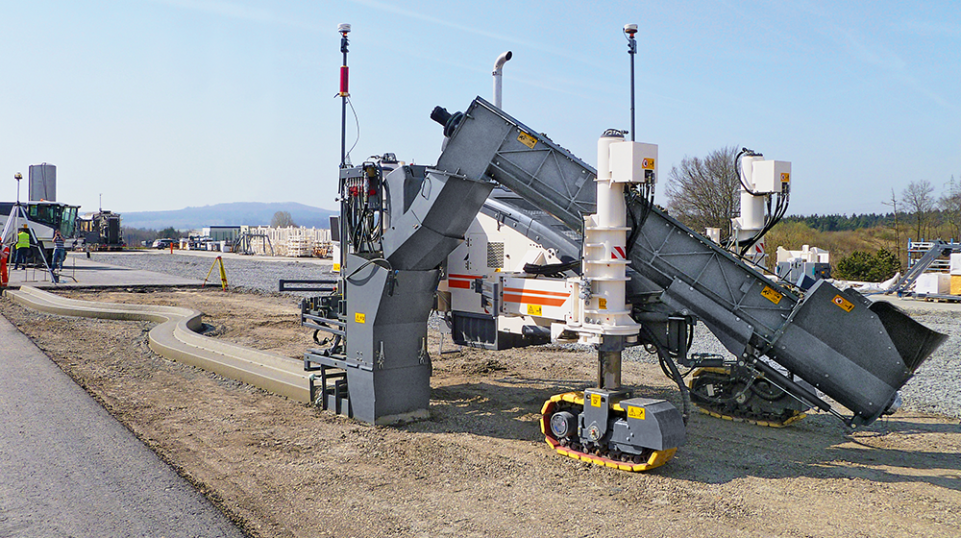
Electronic slope control
Perfect paving results are guaranteed
thanks to the electronic slope control developed by WIRTGEN on the basis
of the “Rapid Slope” cross slope sensor. Optimized control technology
enables the innovative slope control system to achieve as yet unmatched
dynamics and precision. Significantly shorter machine response times are
refl ected in the precision and quality of the completed concrete
product. The WIRTGEN cross slope system can be relied on to quickly
level out any vibrations or ground irregularities.
High-precision cutting depth control
Selective mining driven to the max
Precise control of the cutting depth is a
vital requirement that surface miners need to meet for selective
mining, the production of level surfaces, and grading. Cutting depth and
cross slope are set and controlled via the hydraulic height adjustment
feature of the track units.
Control systems
- Manual or automatic adjustment of the cutting depth using the hydraulic height adjustment feature of the track systems.
- Cutting depth control by scanning the level of an existing surface using sensors installed at the side plate.
- One or two masts equipped with laser
receivers can be installed on the left and right side of the machine.
These laser receivers are connected to the automatic cutting depth
controller. Hence very levelled horizontal surfaces and slopes can be
generated.
- When a GPS receiver is connected to
the automatic cutting depth controller, predefined profiles can be cut
after programming the receiver accordingly.
Công nghệ khác
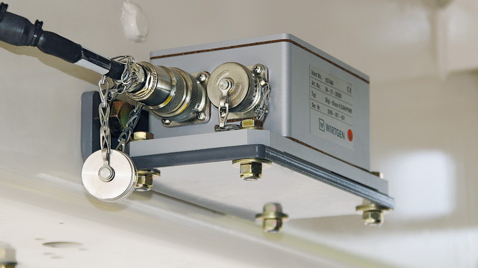
WIRTGEN sensors and scanning equipment